After a few nights of soldering I've managed to get a new prototype version up and running. This as mentioned in the previous post will become the new live test version.
(8th July 2012)
Added the RS232 communication module to the controller (not shown in this pic) and it works a treat! so this week it's just finishing off the firmware coding.
(13th July 2012)
The controller to external eeprom code is now complete, which basically means when you select a firing programme, the programmes are displayed dynamically from the eeprom.
(14th July 2012)
I finished the last part of the programme data re-code last night - what a pain in the arse that was! I completely filled up the area left for writing any more code!, In order to finish off the core routines I had to drop exisitng features; I was very dissapointed about this but I guess this isn't a PC software application, so I don't enjoy the freedom of tens of megabytes of free programming space.
(15th July 2012)
Finished some changes to the PC programme compiler; the compiler allows me to compile programmes and now configuration files for the controller. I'm currently now working on the PC communication code. All the tools described form the drivers of the hardware. From a user point-of-view these should be invisible and only the front-end tools will be visible.
(16th July 2012)
Progress on the PC RS232 code is coming along nicely; I've created a simple console application and added a couple of commands already, once complete I plan to move all the code into a library which all the applications described above can use, this will allow them to directly access the controller.
(Aug. 2012)
Bad month this month, I managed to kill 2 x LCD displays and a microcontroller!! Found a timing issue with the eeprom; looks like more head bashing with the bit-bashing i2c. Got to order more LCDs and microcontrollers from China!
(03 Sept.2012)
Last night I fixed the nasty timing bug in the eeprom i2c bus, this only effected the eeprom.. I discovered this whilst testing the RS232 PC routines when occasionally it was returning bad data. Back on with testing / tidying the PC software side.
(02 Oct. 2012)
I'm pretty satisfied the firmware is solid enough for live testing. I had a small problem with the programme upload code not working, but it just needed a few tweaks here and there.
The next job is to tidy up the PC code and software. I want a real nice way of creating profiles; at the moment it's all done in XML and compiled use a special command line tool. Although this method works, it's far too techie orientated for a typical users to follow. I've got some good ideas for this so it should interesting to see where it goes!
(11 Feb. 2013!)
Well, it's Feb! and things are moving along once again; I've created another version of the proto2 but this time it's small enough to fit into the nice blue box. The pic below shows the larger one and the smaller one. I couldn't fit it all on to one small board so I had to make two, the other one, which isn't shown in the pic has all the power rails on.
 Last night I powered up the uC, LCD display and flash memory; so far, so good! tonight I plan to add the clock and thermocouple chip and then make sure the RS232 PC communication side of things is working.
(12 Feb. 2013)
Got the clock working and the RS232 Communication; one thing I noticed is that the RS232 module appears on the PC as a different COM port, which means potentially you could control multiple kiln controllers from one PC, which I thought was pretty cool! Tonight I plan on adding the thermocouple IC chip and then giving it a final test before I finally put it in the box and fix it to the kiln.
(13 Feb. 2013)
Added the thermocouple chip, and no joy, for some reason the temperature is reading 0! I'll check it out tomorrow.
(14th Feb.2013)
Thermocouple chip is now working! I missed a wire connection between 2 of the pins. So all I need to do is to tweak the trimmers to make sure it's reading correctly and use my thermocouple simulator to simulate some temperatures.
(8th July 2012)
Added the RS232 communication module to the controller (not shown in this pic) and it works a treat! so this week it's just finishing off the firmware coding.
(13th July 2012)
The controller to external eeprom code is now complete, which basically means when you select a firing programme, the programmes are displayed dynamically from the eeprom.
(14th July 2012)
I finished the last part of the programme data re-code last night - what a pain in the arse that was! I completely filled up the area left for writing any more code!, In order to finish off the core routines I had to drop exisitng features; I was very dissapointed about this but I guess this isn't a PC software application, so I don't enjoy the freedom of tens of megabytes of free programming space.
(15th July 2012)
Finished some changes to the PC programme compiler; the compiler allows me to compile programmes and now configuration files for the controller. I'm currently now working on the PC communication code. All the tools described form the drivers of the hardware. From a user point-of-view these should be invisible and only the front-end tools will be visible.
(16th July 2012)
Progress on the PC RS232 code is coming along nicely; I've created a simple console application and added a couple of commands already, once complete I plan to move all the code into a library which all the applications described above can use, this will allow them to directly access the controller.
(Aug. 2012)
Bad month this month, I managed to kill 2 x LCD displays and a microcontroller!! Found a timing issue with the eeprom; looks like more head bashing with the bit-bashing i2c. Got to order more LCDs and microcontrollers from China!
(03 Sept.2012)
Last night I fixed the nasty timing bug in the eeprom i2c bus, this only effected the eeprom.. I discovered this whilst testing the RS232 PC routines when occasionally it was returning bad data. Back on with testing / tidying the PC software side.
(02 Oct. 2012)
I'm pretty satisfied the firmware is solid enough for live testing. I had a small problem with the programme upload code not working, but it just needed a few tweaks here and there.
The next job is to tidy up the PC code and software. I want a real nice way of creating profiles; at the moment it's all done in XML and compiled use a special command line tool. Although this method works, it's far too techie orientated for a typical users to follow. I've got some good ideas for this so it should interesting to see where it goes!
(11 Feb. 2013!)
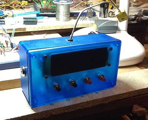
Well, it's Feb! and things are moving along once again; I've created another version of the proto2 but this time it's small enough to fit into the nice blue box. The pic below shows the larger one and the smaller one. I couldn't fit it all on to one small board so I had to make two, the other one, which isn't shown in the pic has all the power rails on.

(12 Feb. 2013)
Got the clock working and the RS232 Communication; one thing I noticed is that the RS232 module appears on the PC as a different COM port, which means potentially you could control multiple kiln controllers from one PC, which I thought was pretty cool! Tonight I plan on adding the thermocouple IC chip and then giving it a final test before I finally put it in the box and fix it to the kiln.
(13 Feb. 2013)
Added the thermocouple chip, and no joy, for some reason the temperature is reading 0! I'll check it out tomorrow.
(14th Feb.2013)
Thermocouple chip is now working! I missed a wire connection between 2 of the pins. So all I need to do is to tweak the trimmers to make sure it's reading correctly and use my thermocouple simulator to simulate some temperatures.